Simple Bracket#
Objective#
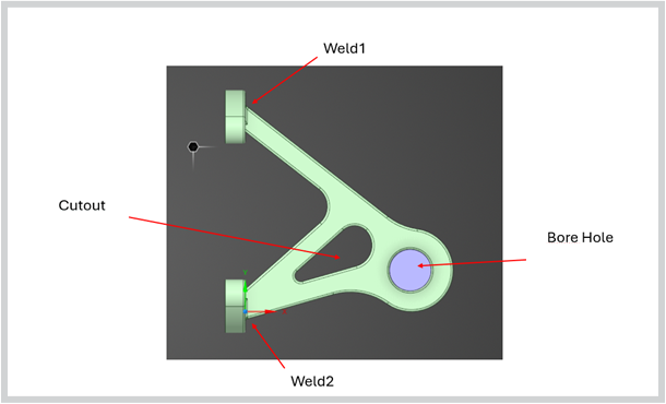
This example describes the analysis of a bracket. The assembly consists of two parts, the bracket with a bored hole with cylindrical bolt, through which a force load is applied. The bolt is connected to the bracket via a nonlinear frictional contact.
The focus of the analysis is on the deformation results and on the equivalent von Mises stress of the bracket.
Parameter and limits#
Boundary conditions |
Description |
Min. Value |
Max. Value |
|---|---|---|---|
Bore_hole_x |
Position of bolt (x) |
85 |
95 |
Bore_hole_y |
Position of bolt (y) |
15 |
25 |
Cutout_fillet_r |
Radius at Cutout |
2 |
8 |
Cutout_r |
Cutouts length |
0.1 |
2 |
Weld_r1 = Weld_r2 |
Radii of weld seams (weld1 = weld2) |
0.5 |
3 |
Model Outputs#
Displacements (x, y, z)
Von Mises Stress
Download case data#
This tutorial uses sample simulation case data provided in a ZIP archive named bracket.zip.
To access the sample case data, download the Bracket.zip , save it to your machine and unzip the archive.
The bracket.zip contains a dataset folder containing subdirectories with the training data.
Each sub folder contains exactly two files:
surface.vtp file containing geometry and 2D simulation data
boundary.json file describing the operating conditions
Launch the application#
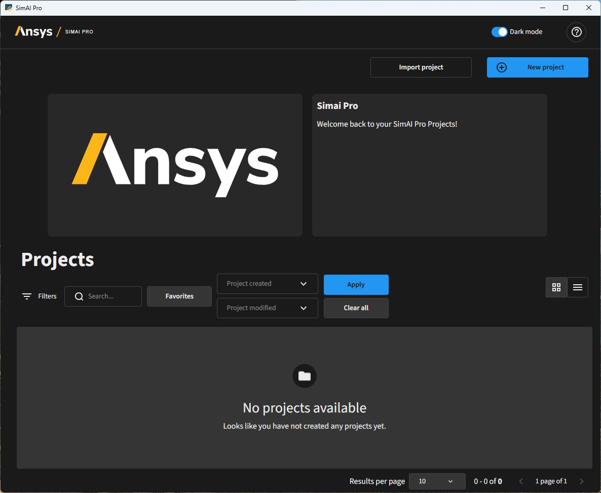
To launch the SimAI Pro application, double-click the SimAI Pro 2026 R1 shortcut on your desktop:

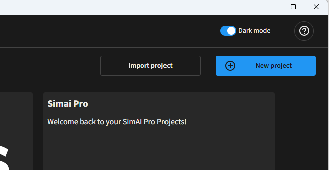
The Projects dashboard opens.
Create a project#
As a first step you must create a new project
In the Projects dashboard, click New Project
Define a project name, for example: “Bracket Example”
Add a project description (optional): “Tutorial Project”
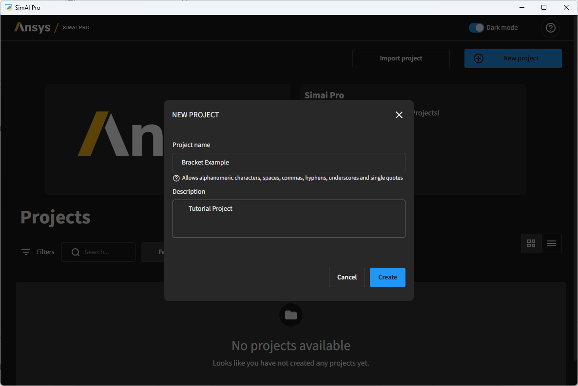
Click Create
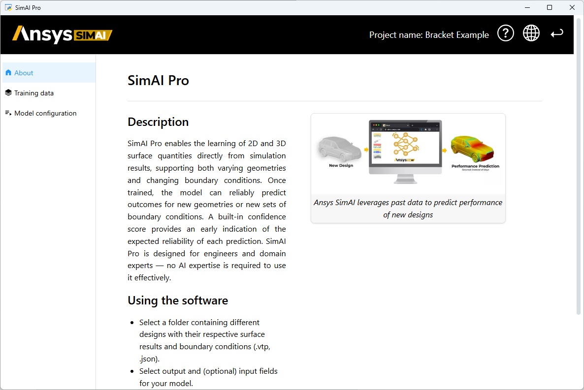
The project is created and opened in the main view
Add the training data#
Import all directories from the dataset path as training data. Each subdirectory should contain the files for one training data sample.
Use the Training data tab in the navigation panel.
Click Select data folder.
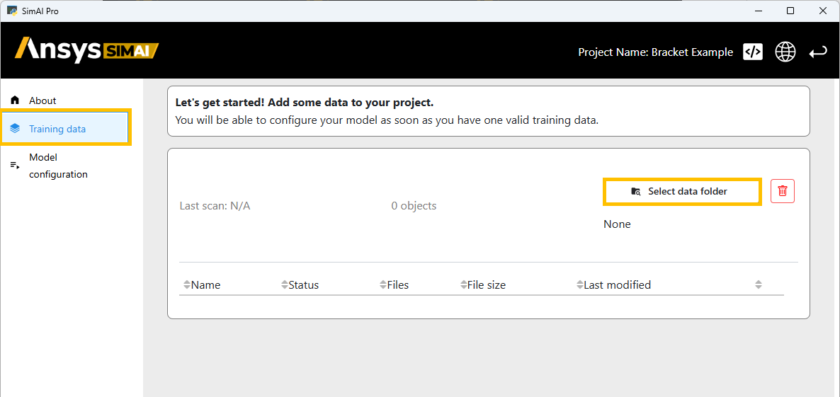
Pick the dataset folder from your disc. Each subdirectory should contain the files for one training data sample.

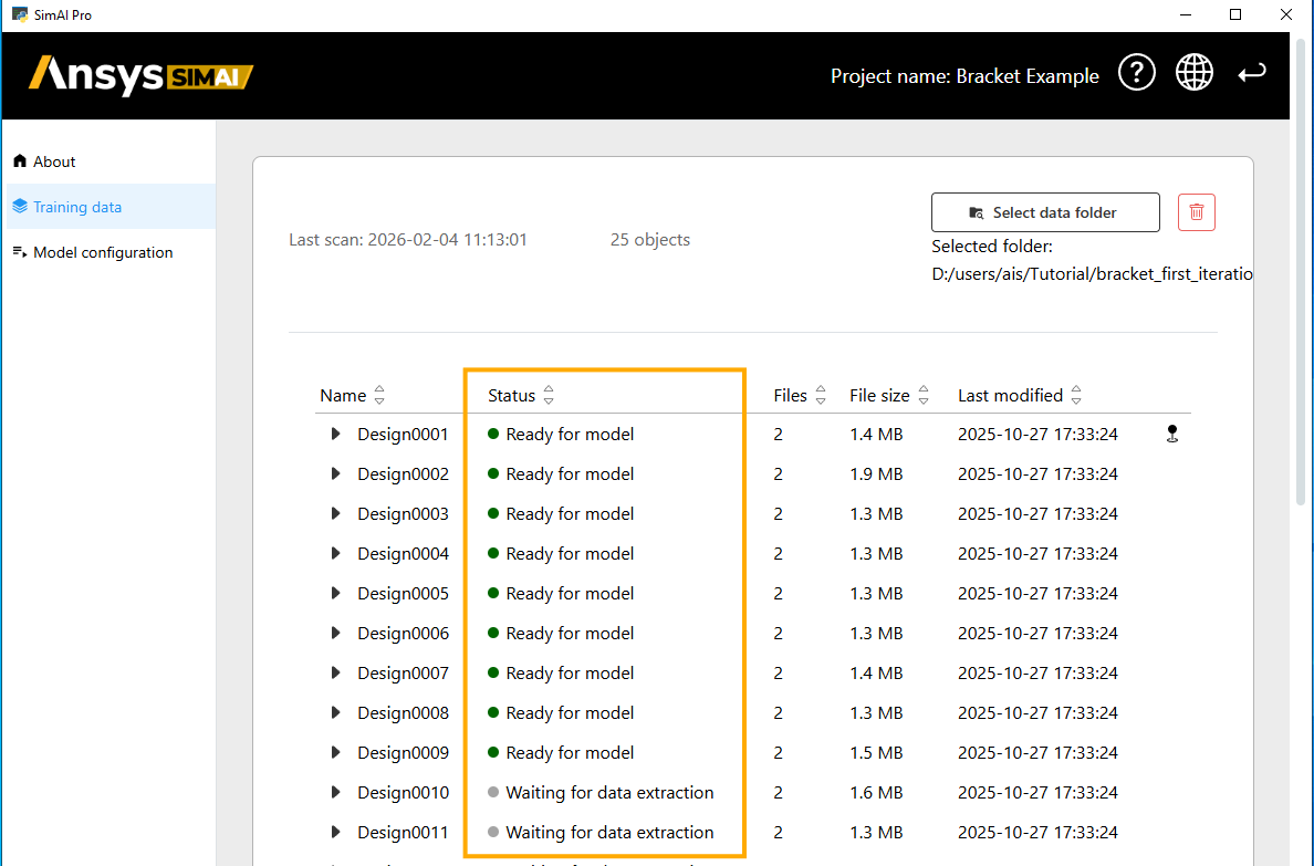
After importing, the SimAI Pro application needs to process the training data. Get all data in the current project and wait for them to be ready.
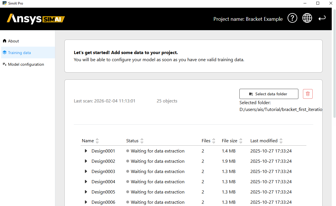
Check the project’s data processing status and wait until the data are “ready for model.”
Note
The bracket.zip provided for this tutorial has valid formatting. Before importing any other data, make sure that the folder structure and data are correctly formatted, as described in Verify input files.
Define parameters#
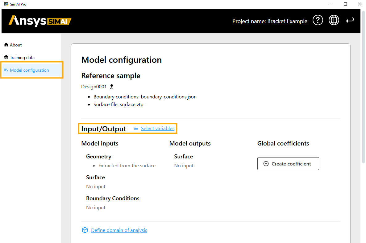
Define which surfaces and boundary conditions the model will use as inputs and as outputs.
Use the Model configuration tab in the navigation panel.
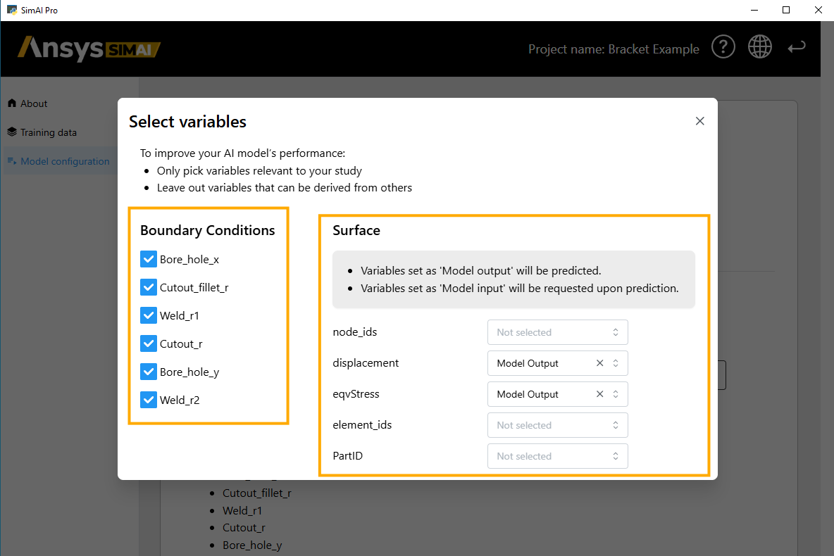
Click Select variables.
Select the Boundary conditions that are relevant for training. In this tutorial, select all displayed parameters.
On the right side, select displacement and eqvStress as output variable. These two results will be predicted after model training.
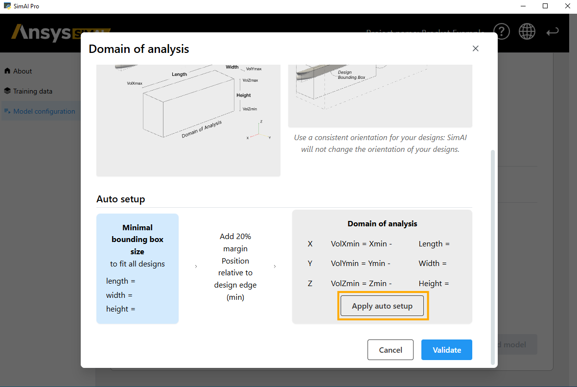
Domain of analysis#
The Domain of Analysis (DoA) is a rectangular volume that encompasses all your designs:
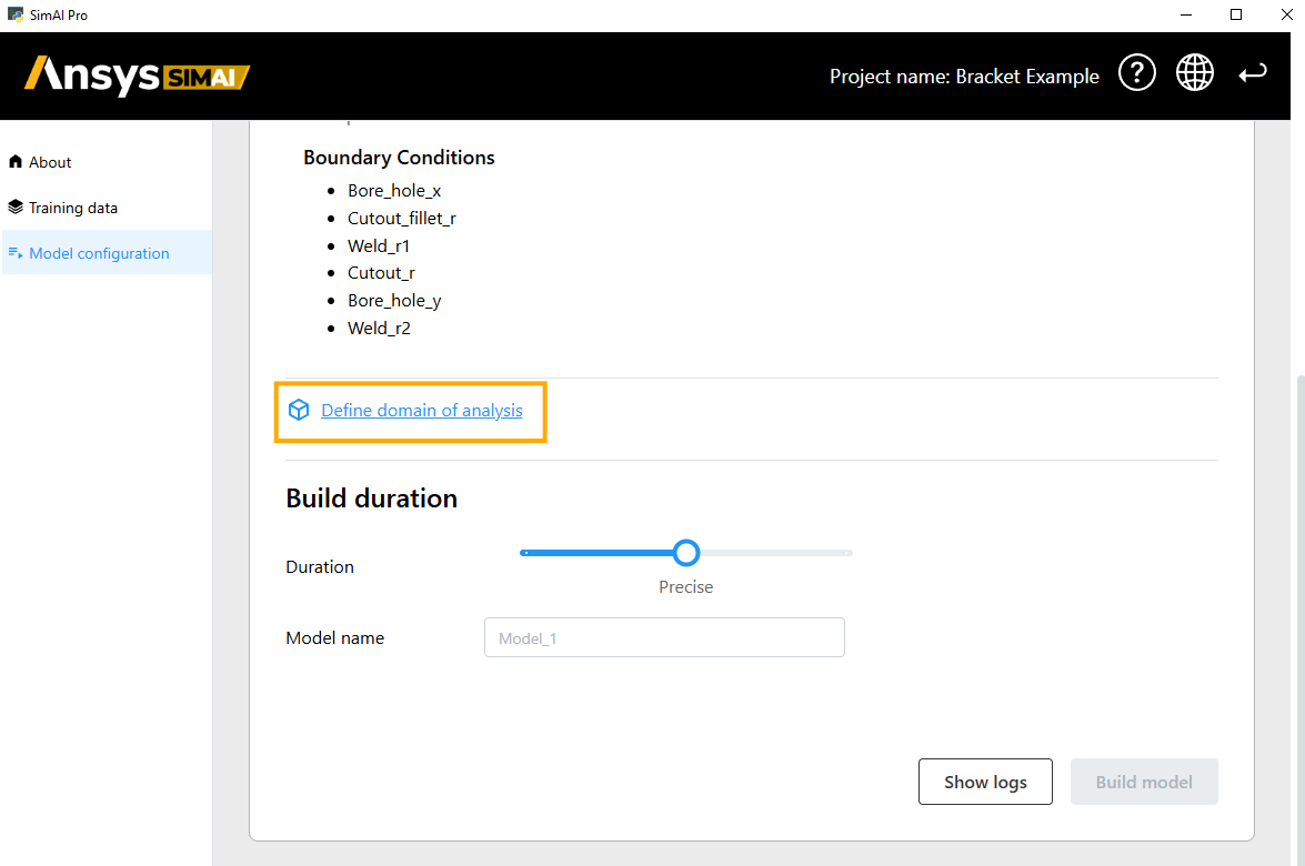
Click Define domain of analysis
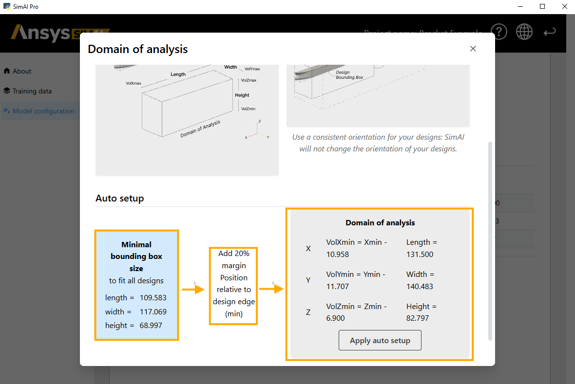
Use the Apply auto setup function. The SimAI Pro application automatically:
Calculates the minimal bounding box size,
Adds a margin of 20% to the design edge,
Defines the Domain of Analysis based on the previously calculated values.
Build duration#
The build duration determines the training time of your AI model, and as a result the accuracy of your analysis.
In this case, use Less precise to accelerate the training and receive results faster.
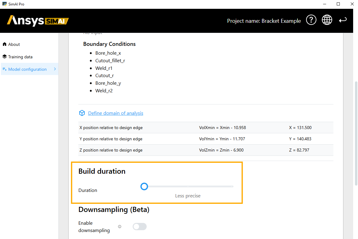
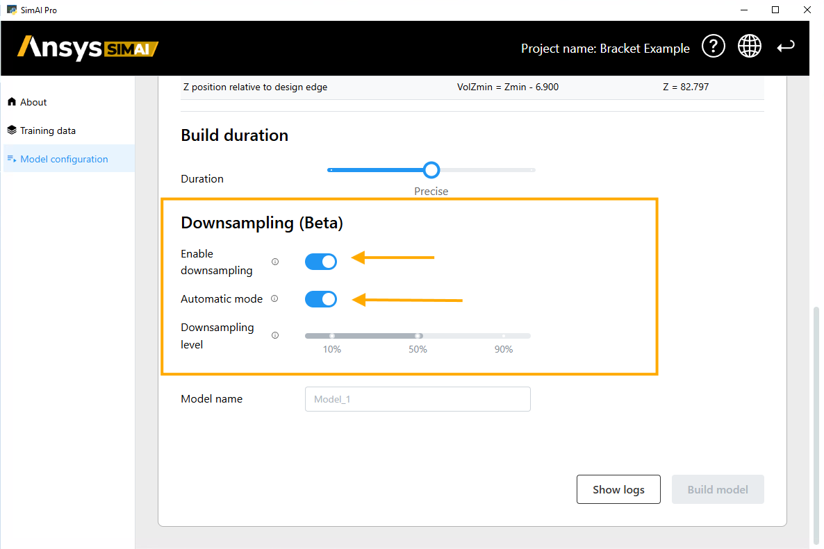
Downsampling (Beta)#
If you enabled the downsampling functionality, the standard UI for building models is extended. For more information, see Enabling Downsampling (BETA).
For a first and fast training Enable downsampling and use Automatic mode. The SimAI Pro application computes a downsampling factor to fit the dataset within 70% of available GPU memory or RAM.
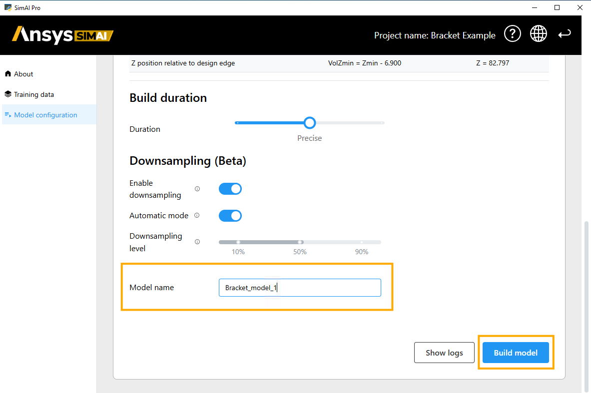
Build model#
You are now ready to build the model.
Enter a Model name.
Click Build model.
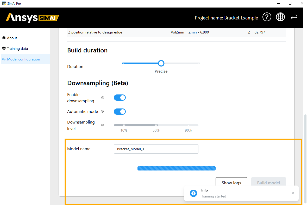
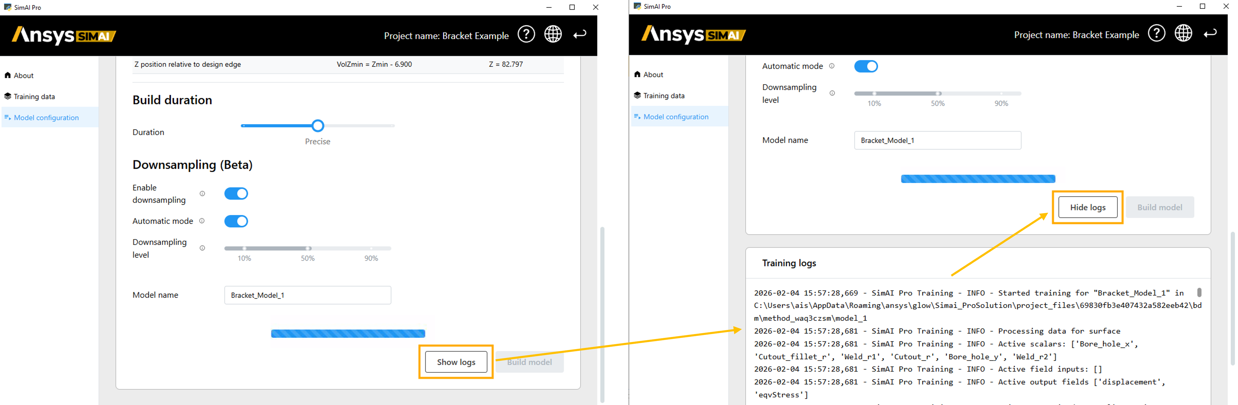
After the training has started, the training logs can be tracked using the Show log button.
Review quality criteria#
Once the training is finished, a new panel item is created in the navigation panel with the model name that was previously assigned.
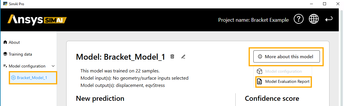
Click on the model Bracket_Model_1
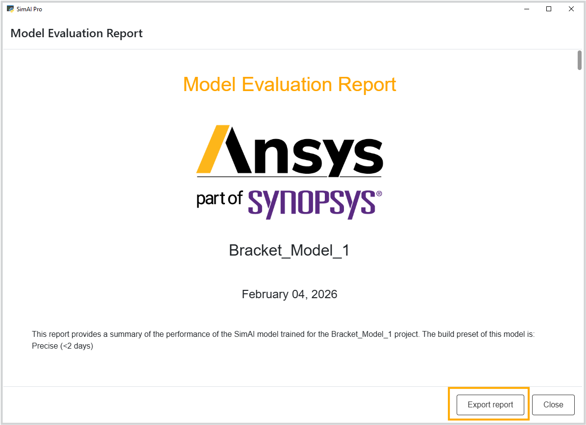
Check the button More about this model and select Model Evaluation Report. For more information, see Model Evaluation Report in the User guide.
Review the summary of the performance of the SimAI Pro model trained for the Bracket_Model_1 project.
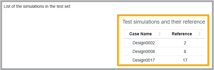
To check the quality of the AI model, you can use the datasets that were not used for the model training for model prediction.
These datasets are listed in the report under section Input Data -> List of the simulations in the test set:
Running a prediction#
The prediction is performed in the same project where the training data are located, and the AI model was created.
Select Bracket_Model_1 under Model configuration on the left side of the main view of your project. This new panel item is automatically created once your AI model is ready to be used.
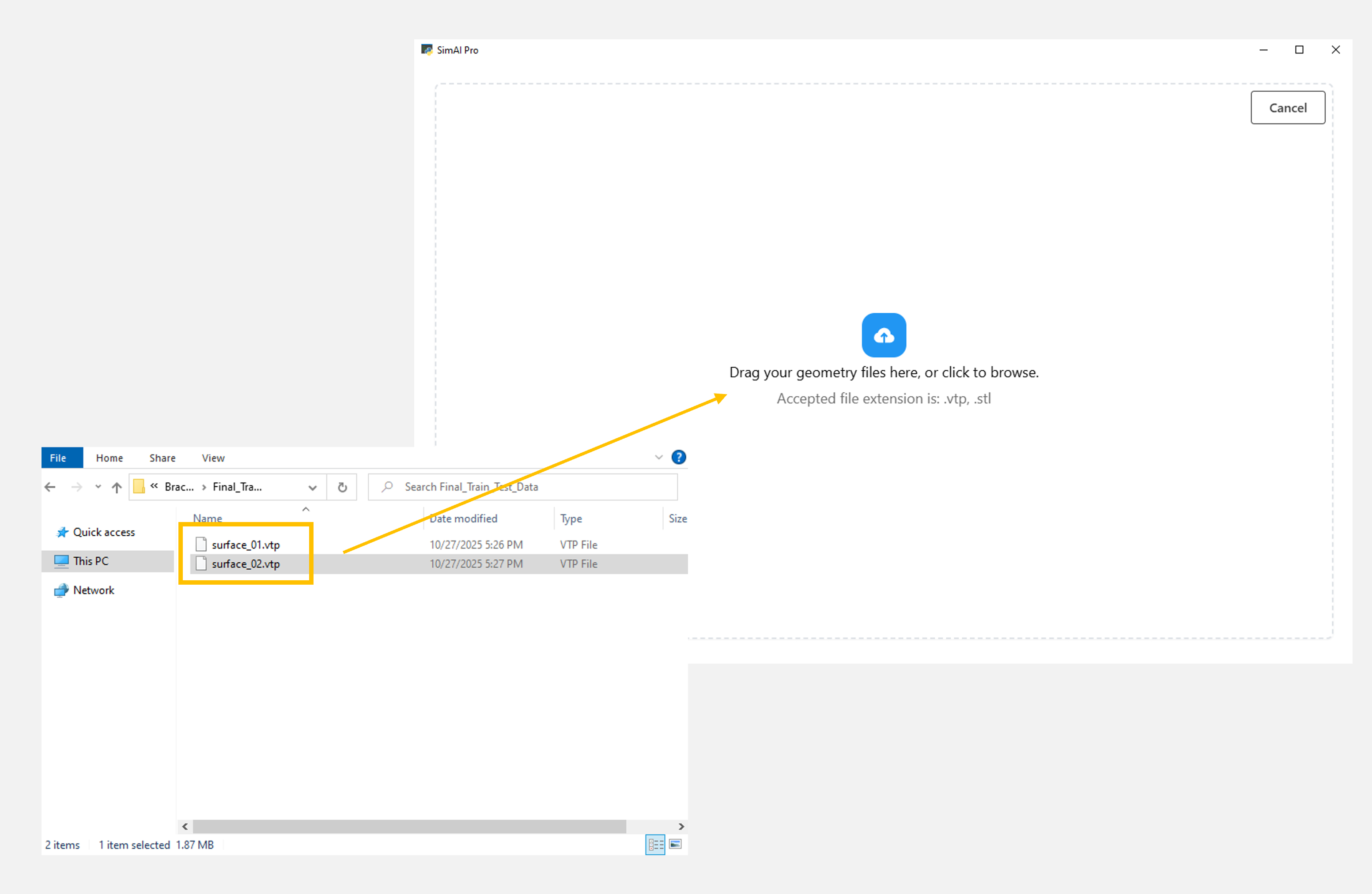
Click the plus button next to Add/remove new geometries to import a new geometry file for which you want to run a prediction. For more information about the accepted files, see Geometries .
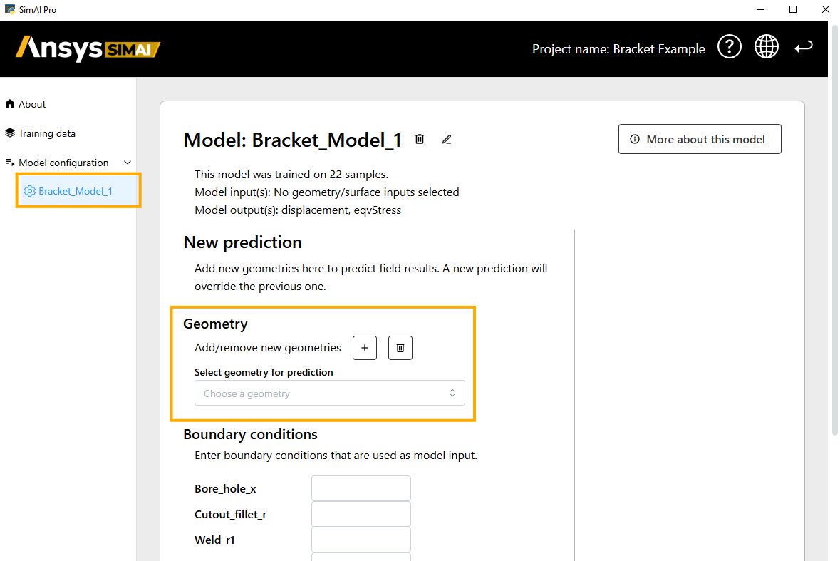
Browse or drag the geometry file or files from your device.
Select the geometry for which you want to run a prediction.
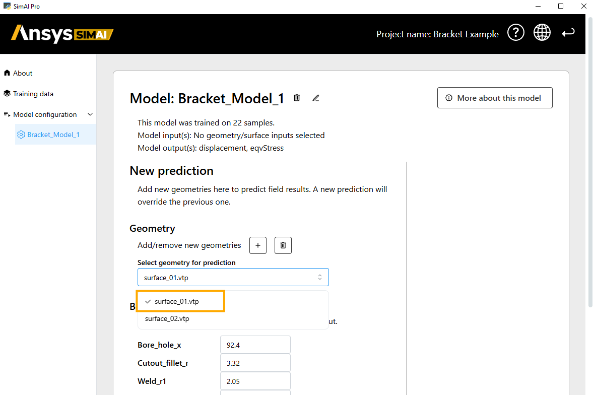
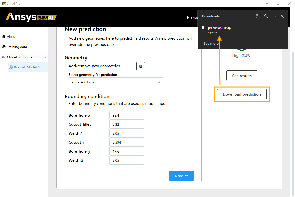
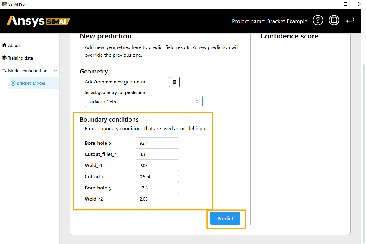
Enter the values for the Boundary conditions for which the prediction should be generated.
Click Predict.
Review the predicted results#
Now, analyze how the model is performing on the selected geometry surface_01.vtp.
The Confidence score on the right-hand side does not guarantee correctness but a value of 0.98 indicates high certainty and suggests the model has seen similar past patterns that led to this answer frequently.
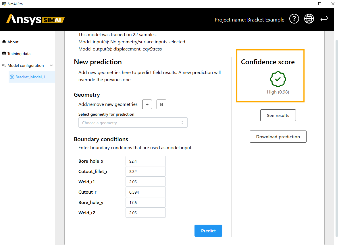
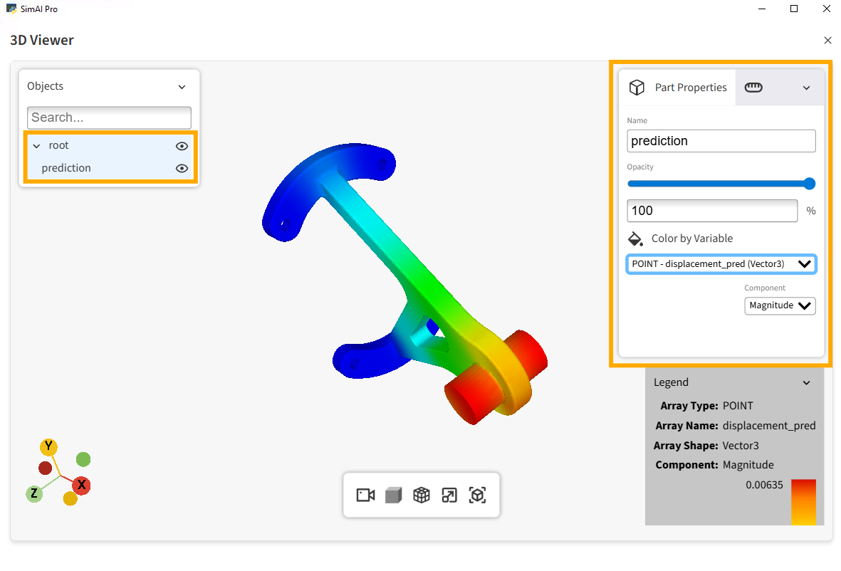
You can review the predicted results using the integrated 3D-viewer. Click See results.
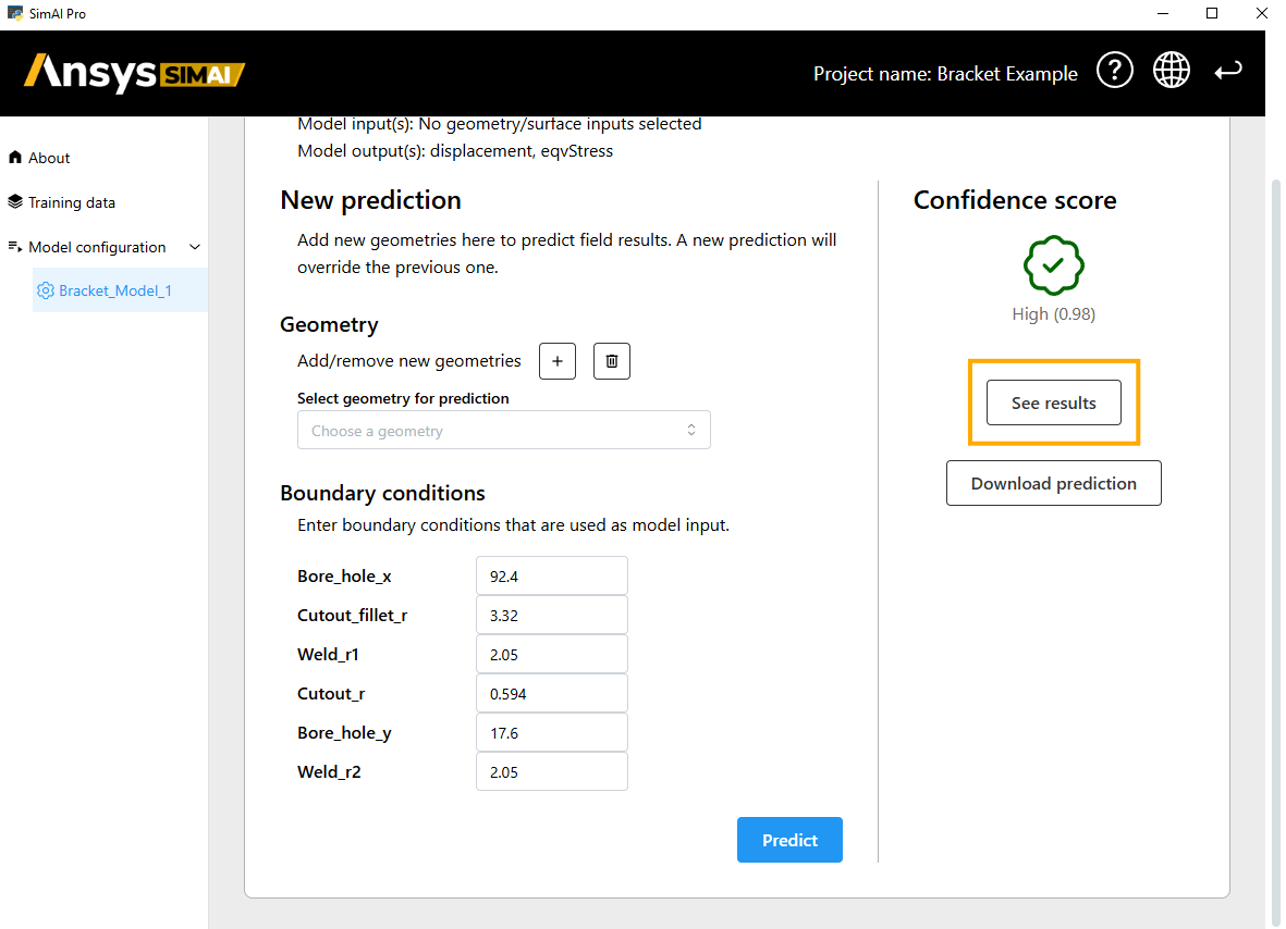
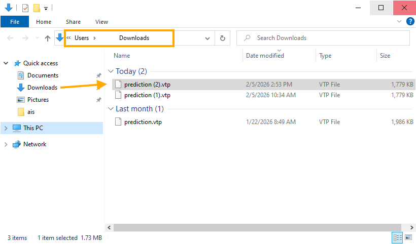
Download the prediction for further postprocessing or usage.